Surface Finish and Machining Tolerances: How to Specify and Measure Them
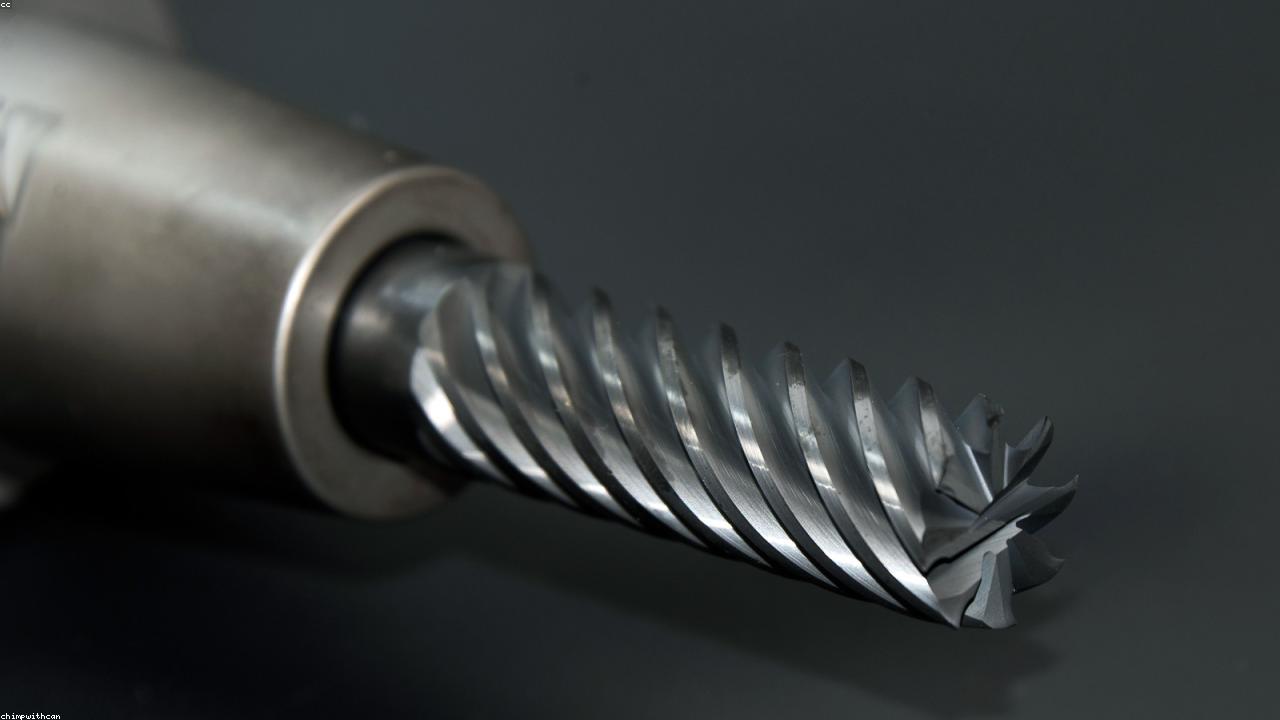
A machined part carries two separate promises. The tolerance says how close the part is to the size and shape the drawing demands — how big the bore really is, how square the face really is. The surface finish says how the surface feels at a microscopic scale — how smooth the wall of that bore is, how fine the tool marks are. Beginners conflate them, and the conflation is expensive: a part can be perfectly on dimension and still fail because its surface leaks, or perfectly smooth and still fail because it is the wrong size. Roughness and tolerance are different qualities, measured differently, fixed differently — and the drawing is the contract that must say both, clearly enough that the machinist and the inspector read the same intent.
This guide is the reference for specifying and measuring both. It explains the roughness vocabulary (Ra, Rz and the rest), the tolerance and geometric (GD&T) system it lives in, how finish and tolerance interact, what each machining process can realistically achieve, and how to write a drawing a shop can actually hit — then measure it without fooling yourself. It is the quality companion to the wider guides library: finishing practice explains how feeds set finish, the machine-selection guide treats your worst-case tolerance as a buying criterion, and the spec-sheet guide explains the machine’s own accuracy claims. Term definitions are in the CNC glossary.
The surface roughness vocabulary
Every machined surface, however smooth it looks, is a landscape of microscopic peaks and valleys left by the cutting edge. Surface roughness is the standardised measure of that landscape, and it is defined by international standards — ISO 4287 in Europe and much of the world, ASME B46.1 in North America. The numbers come from a trace of the surface profile, and each parameter summarises that trace differently:
| Parameter | What it measures | What it is good for |
|---|---|---|
| Ra | The arithmetic average of the profile’s height deviations from its mean line — “the average bump size” | The everyday roughness callout; simple, comparable, the default on most drawings |
| Rz | The average of the tallest peak-to-valley heights across five sampling lengths | Catching the extremes Ra hides — scratches, deep valleys, tool-wear damage |
| Rq (RMS) | The root-mean-square version of Ra — more sensitive to large deviations | Research and fatigue work where the statistic matters |
| Rt / Rmax | The single largest peak-to-valley height anywhere in the trace | Sealing and contact surfaces where one deep scratch causes a leak |
The rule most shops carry is that Rz runs roughly four to seven times Ra for ordinary machined surfaces — but that is a rule of thumb, not a conversion. Ra and Rz measure different things, so there is no exact mathematical translation between them: a surface with one deep scratch can have a perfectly good Ra and a badly failing Rz, which is exactly why Rz exists. If a single flaw can make the part fail (a seal face, a fatigue-critical surface), specify Rz or Rmax; if you only care about the general quality, Ra is the honest choice.
What the number actually decides
Roughness is not cosmetic. The surface texture a part carries into service decides how it behaves:
- Friction and wear. Rougher surfaces drag and wear faster on sliding and rotating contacts; smoother surfaces slide. But too smooth can be wrong too — many plain bearings and seals rely on microscopic valleys to hold lubricant.
- Sealing. A gasket or O-ring surface needs a controlled roughness: too rough and the surface leaks past the peaks; paradoxically, too smooth a metal face can fail to grip a gasket that relies on texture. Values around or below Ra 3.2 µm are common for gasket faces.
- Coating and adhesion. Paint, anodising and adhesives often bond better to a slightly textured surface than a mirror one.
- Fatigue. Roughness peaks and valleys are stress concentrators. A fatigue-critical part — a shaft, a spring, a component under cyclic load — can fail from a scratch that a cosmetic surface would tolerate, which is why fatigue parts get both fine Ra and an Rz or Rmax check that no single flaw escapes.
- Fit and measurement. Roughness sits inside the tolerance zone: if you specify a clearance of a few microns on a surface that is rough by microns, the peaks determine the real fit, not the nominal dimension.
The mental model to hold: roughness is the third and finest of three texture scales — form (is the face flat at all?), waviness (is there a gentle undulation?), roughness (how fine are the tool marks?). They are filtered apart in measurement and fixed by different things. A mirror-smooth surface can be badly out of flat, and a beautifully flat surface can be too rough to seal.
The tolerance system: two languages
Where roughness describes the surface, tolerances describe the geometry, and machining drawings speak two dialects of it.
Linear and size tolerances are the everyday ± numbers. When a drawing gives no explicit tolerance, a general tolerance standard applies — ISO 2768 is the common one, with classes from fine to very coarse, and the medium class (a few tenths of a millimetre on modest sizes) is the frequent default for unmarked dimensions. The discipline is to leave general tolerances on non-critical features and add explicit callouts only where function demands them — mating bores, bearing seats, critical locations. What machining can hold is a range, not a point: general three-axis work typically lands within roughly ±0.05–0.1 mm on accessible features, tighter with care; precision work reaches ±0.01–0.025 mm under controlled conditions; and tolerances tighter than that — the ±0.005 mm class and below — normally require the secondary processes (grinding, honing) that also change the finish story.
Geometric dimensioning and tolerancing (GD&T) — ASME Y14.5 in North America, ISO 1101 internationally — is the other language, and it exists because ± dimensions fail at describing relationships. A hole pattern toleranced with stacked ± dimensions accumulates error across the chain and says nothing about where the pattern sits relative to the part’s function; GD&T describes a tolerance zone — position, flatness, perpendicularity, runout — anchored to datums, the theoretically exact reference features the part is measured from. Most drawings use only a handful of the symbols — true position for hole patterns, flatness for mating faces, perpendicularity, profile, runout — and the feature control frame is read left to right: the symbol, the tolerance value, and the datums it is measured relative to. Datum order matters: the primary datum locks the part first, and swapping the order can change what the inspector measures even on the same physical part. Choose datums the way the part is used and fixtured — the face that seats in the assembly, the bore that locates it — not the prettiest surface on the drawing.
When the drawing says “±0.05 here, GD&T there,” the rule underneath is one: say what the part must do to work, not what is easiest to draw. Position callouts on hole patterns often let the machinist hold a looser absolute tolerance through material-condition bonuses than a chain of stacked ± dimensions ever could — GD&T frequently buys capability rather than costing it.
How finish and tolerance interact
The two systems meet in three places a specifier must respect:
Roughness lives inside the tolerance zone. The peaks of a rough surface eat into the dimensional tolerance. A bore specified at 20.000 ±0.005 mm with a rough wall does not have a meaningful 0.005 mm clearance to its shaft — the peaks carry the load and the valleys are dead space. Fine tolerances on a sealing or fitting surface imply a finish fine enough that the surface texture does not dominate the fit, which is why critical fits and fine finishes travel together.
Finish is set by process, tolerance by geometry — and they pull different levers. On a turned or milled surface, feed and tool nose radius largely set the roughness — the theoretical turning rule is that Ra scales with the square of the feed divided by the nose radius, so a finer finish comes from a lighter feed or a larger nose radius — while dimensional tolerance is set by the machine’s accuracy, stiffness and thermal behaviour. They are fixed separately: you can finish-pass a surface smooth without moving its position, and you can hold position precisely on a surface still too rough to seal. Our parameters guide treats the finishing pass as exactly this: light cuts for surface, with size and position carried by the machine.
Don’t ask a process for what it cannot give. A roughness callout is a process demand in disguise: Ra 1.6 µm is routine machining, Ra 0.8 µm is a controlled finishing pass, Ra 0.4 µm and below is grinding or finer, and specifying Ra 0.2 µm on a part meant to be milled only is specifying a process the drawing never names. Call out the finish the surface needs, understand what process will be required to hit it, and keep the finish and the tolerance mutually achievable.
What each process realistically achieves
As a rough reference — every figure is a starting band, not a guarantee, because the result depends on the material, the tool, the machine’s condition and the feature’s accessibility:
| Process | Typical Ra (µm) | Typical tolerance (accessible features) |
|---|---|---|
| Rough milling / turning | 3.2 – 12.5 | ±0.05–0.1 mm and above |
| General machining (finish turning, face milling) | 1.6 – 3.2 | ±0.05 mm class |
| Fine machining (finishing passes, reaming, boring) | 0.8 – 1.6 | ±0.01–0.025 mm class |
| Grinding (surface / cylindrical) | 0.1 – 0.8 | ±0.005 mm class |
| Honing, lapping, superfinishing | 0.025 – 0.2 | below ±0.005 mm |
The gradient is the point: as the required finish and tolerance tighten, the process ladder climbs — and so does the cost, not because anyone is overcharging but because each step down means more passes, a secondary process, finer tooling and more measurement. This is where the site’s standing rule about what drives machining cost applies in miniature: tolerance and finish are cost drivers, and the cheapest specification is the loosest one the part can function with. Tighten what functions need — bearing seats, seals, mating interfaces — and leave everything else on the general tolerance and a sensible finish. The parts that cost the least to make well are the ones whose drawings do not demand precision from features that do not use it.
Measuring it honestly
A roughness or tolerance number is only as good as the measurement behind it, and measurement has traps that routinely produce false confidence:
For roughness, the profilometer must be set up right. A stylus profilometer drags a diamond-tipped needle across the surface and computes the parameters from the trace. Three errors dominate. First, direction: run the stylus perpendicular to the tool marks (the lay) — parallel to them the needle rides in the grooves and reports a misleadingly smooth surface. Second, the cutoff (sampling length) must match the roughness being measured, per ISO 4288: the filter length separates roughness from waviness, and leaving the instrument on the wrong cutoff can under-read Ra by half — a surface that is truly Ra 1.6 µm can read as 0.8 µm on too short a cutoff. Coarser surfaces need longer cutoffs. Third, units: Ra 1.6 µm and 63 microinches (µin) are approximately the same surface, and mistaking one unit for the other specifies a surface nearly forty times rougher or smoother than intended. And remember Rz’s reason for existing: one deep scratch barely moves Ra but jumps Rz, so if a single flaw would fail the part, measure the parameter that catches it.
For geometry, match the tool to the tolerance. Size on accessible features is checked with micrometers, calipers and bore gauges; a coordinate measuring machine (CMM) or on-machine probing reads positions, datums and runout relative to the datum frame. The measuring instrument must itself be an order of magnitude more precise than the tolerance it is checking — a tenth-millimetre tolerance cannot be judged by a tool with tenth-millimetre resolution. And the machine’s own accuracy claims, as the spec-sheet guide explains, are measured on an empty machine at a controlled temperature: temperature is the quiet saboteur of all dimensional work, because steel grows and shrinks with every degree — the reference is 20 °C — so a part machined in a warm shop and inspected in a cold one can fail a fine tolerance that is really being met.
How to write a drawing the shop can hit
A well-specified drawing is one where the machinist, the inspector and the designer all read the same requirement. The practice, in order:
- Default sensibly, tighten deliberately. Put a general tolerance (say, ISO 2768 medium) and a general finish note on the drawing, then add explicit callouts only on the features that function — mating bores, bearing seats, sealing faces, critical locations. The rule of thumb: if a feature does not meet another part, question its tolerance.
- Specify roughness where it functions, in the right parameter. General surfaces get an Ra; sealing, contact and fatigue-critical surfaces get Rz or Rmax too, because they need to catch the single flaw.
- Use datums and GD&T for relationships. Anchor positions and orientations to the datums the part is used and fixtured from, use true position for hole patterns instead of stacked ± chains, and never write a datumless geometric callout that leaves the inspector guessing what the measurement is relative to.
- Keep finish, tolerance and process consistent. Don’t put Ra 0.2 µm on a surface you intend to mill, and don’t ask ±0.005 mm from a process that cannot hold it — name the finish that implies the process you expect.
- Define the measurement when it matters. If two shops would measure the callout differently — roughness cutoff, datum order, temperature — say which way you want it read. The drawing is a contract, and an ambiguous contract is enforced by whoever inspects it.
Frequently asked questions
Should I specify Ra or Rz? Specify Ra for general surface quality — it is the everyday default, simple and comparable. Specify Rz (or Rmax) when the extremes matter: sealing surfaces, contact faces, fatigue-critical parts where a single deep scratch or peak would cause failure. Ra is an average and can hide one bad flaw; Rz is built to catch it. They are related by a rough four-to-seven-times rule of thumb, not a conversion, so never convert one to the other and expect it to hold.
What tolerance and finish can standard CNC machining actually hold? As indicative bands: general three-axis work typically lands around ±0.05–0.1 mm with a finish of roughly Ra 1.6–3.2 µm on accessible features; precision work reaches about ±0.01–0.025 mm with Ra 0.8–1.6 µm through controlled finishing; and the ±0.005 mm class, or Ra 0.4 µm and below, generally needs grinding and the other secondary processes. The real limits depend on material, feature shape, and the machine’s condition — which is where the machine’s own accuracy specifications and a test part settle it.
Why does a finer finish or tighter tolerance cost more? Because each step down the process ladder means more work: lighter finishing passes, secondary operations like grinding, finer tooling, more inspection — and more risk of a part failing inspection and being remade. The cost climbs the same ladder the capability does. The answer is not to avoid tight specifications but to apply them only where the part functions, and to leave non-functional features on a sensible general default.
Is 63 microinches the same as Ra 1.6 µm? Approximately yes — 63 µin is about 1.6 µm. The two unit systems describe the same surface, and confusing them is one of the most common drawing errors: 63 µm is nearly forty times rougher than 63 µin. Always state the units on the drawing or title block, and check them before comparing two suppliers’ readings.
Can I judge surface roughness by eye or feel? Only coarsely. Machined roughness can be compared against reference specimens and surface comparators, which give a rough visual and tactile match, but a reliable Ra or Rz number needs a profilometer — and one set up correctly, perpendicular to the lay and with the right cutoff. For anything where the finish decides whether the part seals, wears or survives fatigue, measure it rather than judge it.
Bottom line
Surface finish and tolerances are two different promises a part must keep, specified in two different languages and measured by two different instruments. Learn the roughness vocabulary — Ra for the everyday surface, Rz and Rmax where a single flaw would fail the part — and the tolerance system beneath it, using GD&T and datums for the relationships that ± dimensions cannot describe. Understand how they interact: roughness lives inside the tolerance zone, finish is set by the process while geometry is set by the machine, and neither is free — each step down the ladder costs more and needs a finer process, so specify the loosest finish and tolerance the part can function with, not the tightest you can imagine. Then measure honestly: perpendicular to the lay, with the right cutoff, in the right units, at a known temperature. Get the specification and the measurement right, and the drawing stops being a hope and becomes a part.
This guide is part of the CNC Media guides library — the quality and metrology reference, deliberately free of prices and of any single supplier’s tolerance table to sell.